X2 Handover: How does it work?
An X2 Handover is used by LTE as well as S1 handovers for User Equipment (“UE”) or mobile phone mobility.
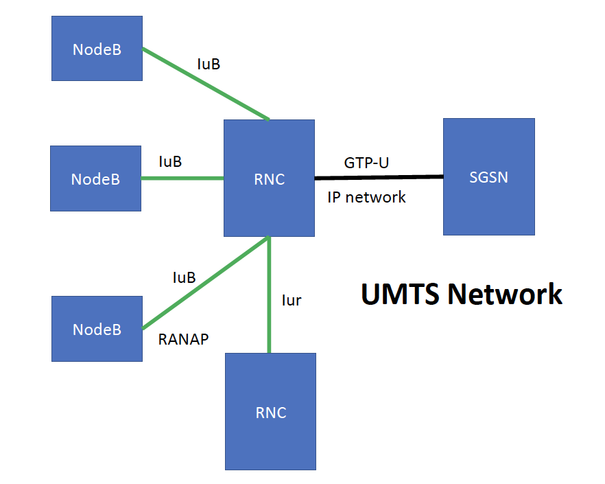
First and foremost, LTE and 5G both share an ALL-IP Architecture. In the past, in UMTS systems or even older systems, mobility consisted in several layers of IuB interfaces from the RNC to the NodeBs. It is not then an ALL-IP network as expected.
In UMTS, the Radio Network Controller (RNC) manages hundreds of NodeBs, all interconnected using the IuB interface and RNC to RNC uses the IuR Interface. The SGSN or Serving GPRS Support Node is in charge of setting up the internet link or GTP-U tunnel from the SGSN tot he RNC. However the IP link will not move although an you can switch from NodeBs, meaning that any soft-handover or hand-handovers that occur between NodeBs does not affect the GTP-U link form the internet to the UE.
In LTE, on the other hand there are many changes, one is that eNodeB is the end-point of the IP link, making it an ALL-IP network. This change requires some redesign to the protocols and specially the insertion of “hard handovers” plus X2 and S1AP Handover protocols that are now based on IP Mobility. As shown in the figure below, X2 interfaces communicate eNodeBs, and S1 links from eNodeBs to S-GWs and S1-MME to the MME. The MME is the Mobility Management Entity which tracks the UE and does paging, as well as updates.
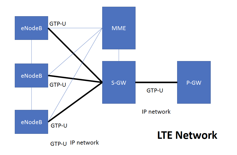
As you can observe, the X2 Interface is key for handoff as this interface is used not only to detect adjacent eNodeBs but also to exchange information as interference and others.
The X2 handover will be illustrated as follows:

The UE has to be in RRC_CONNECTED stated not in RRC_IDLE where a process called “Cell Reselection” i used. Lets Start with 1-6 Steps:
Step 1: Handover Command
As opposed to others, we will start with the Handover Command, which is the an RRC Connection Reconfiguration Message that contains a field called “MobilityConttrolInfo” this field contains the Physical Cell ID to handover to, as well as a list of neighbor cells with their associated “Cell Individual Offsets” that are used for A3, A5 and other events.
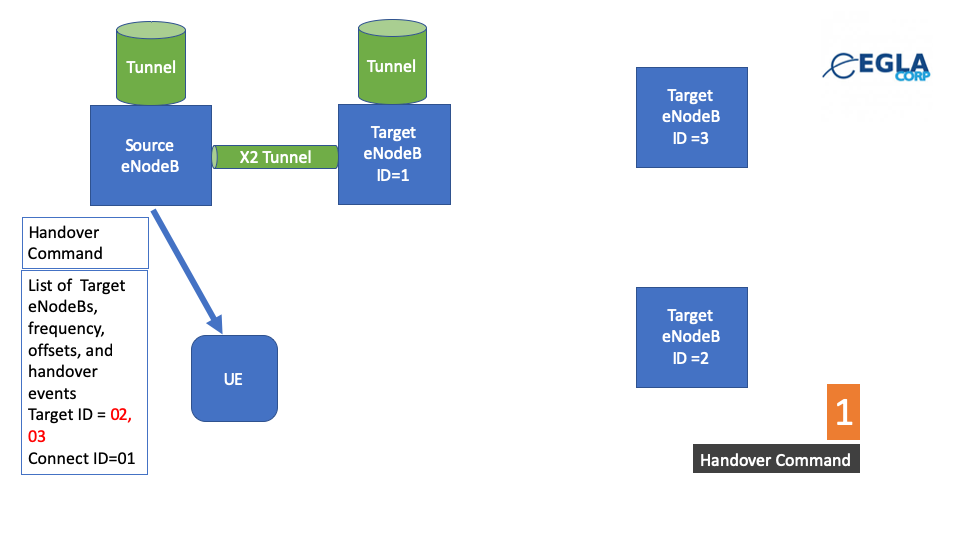
Handover Command
The Handover Command forces the switch from a previous cell to the next cell. Handover can only occur
In this example a Handover Command was issued to connect to eNodeB with ID=1.
An RRC Connection Reconfiguration message may follow with a list of Cell IDs, in this example, 2, 3, and maybe 4, to add to the list to monitor for a measurement report to be created.
Mobility Control Info Structure
This structure can be found in the specification as follows:

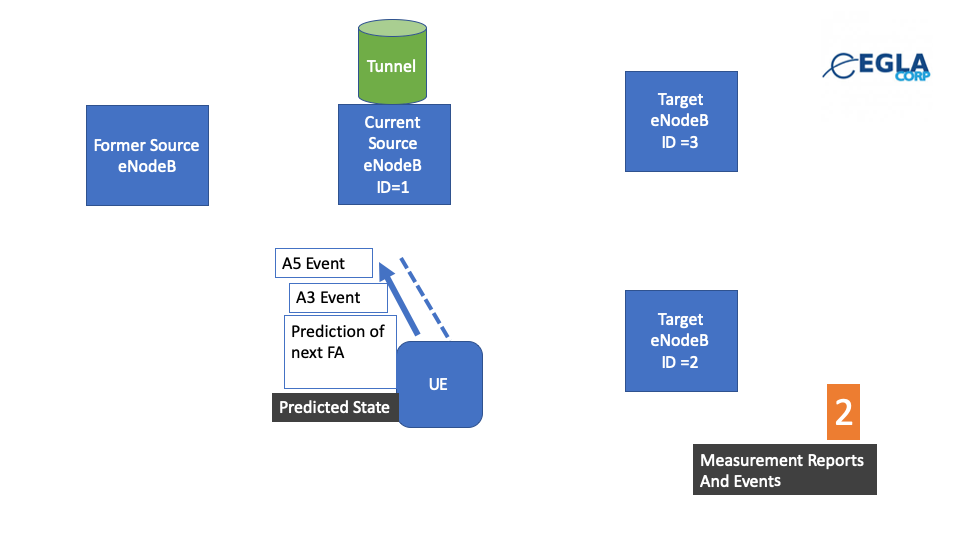
Step 2 : Measurement Reports and Events
As we know, LTE specification defines several reports. In this example we will focus on A5 and A3 events, that are programmed using the Cell Individual Offsets and Frequency offsets found in the specification. Since the device is in “Connected State” Layer 3 filtering is applied to the measurements made by the UE.
The filtering algorithm may use different coefficients that the eNodeB sets as default.

Events and measurements
The state machine inside the UE, is configured by the rrcConnectionReconfiguration message to track all the eNodeBs provided and its frequencies, including applying SIB4 blocks that are submitted by the eNodeB to the target.
In a way the eNodeB is predicting the next state to follow reporting A5 and A3 Events to the eNodeB.
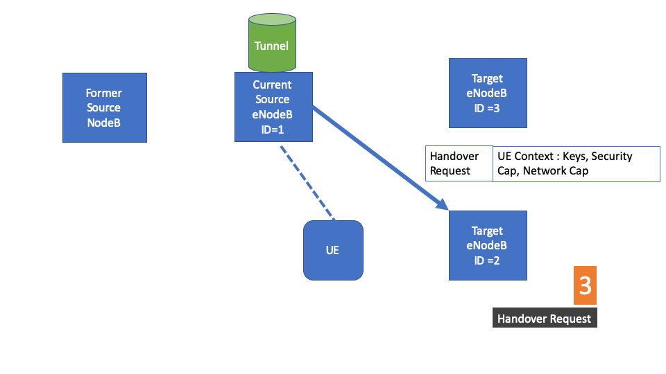
STEP 3: HANDOVER REQUEST
Now it is known by the eNodeB that Handover might be required and decides based on all the events or measurement reports, where to Handoff the UE too, and creates a HANDOVER REQUEST to a a Target eNodeB or the one with ID=2.
STEP 4: Allocation of resources in Target eNodeB
Now that Handover Request is moving forward, a setup for tunnels is created to the Target such that all internet traffic will start flowing tot he Target eNodeB with Cell ID =2
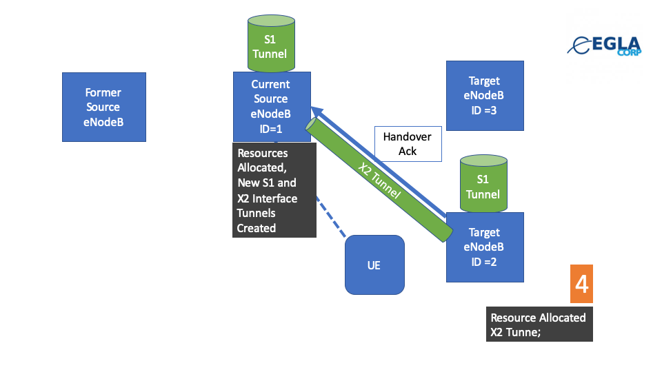
Once this is successful a Handover Acknolwedgement is made to the source and packets start going to the Target, similarly, Downlink and Uplink tunnels start being moved to the target eNodeB with Cell ID = 2
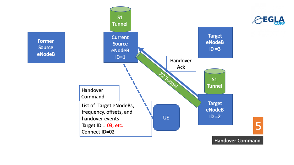
STEP 5. Handover Command to Switch to Target
Exactly as in STEP 1, a Handover Command (in an rrcConnection Reconfiguration message) containing the Target ID = 2 is issued from the Source, also at some point another rrcConnection Reconfiguration message will contain all neighbor nodes with its respective Cell Individual Offests and this process will continue.
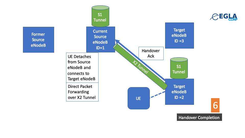
STEP 6. All is switch to the Target and MME is updated of the move.
As a final step of handover, the path switch is complete which is a process called “Late Path Switch” that generates all traffic to move from the Source to the Target eNodeB in its totality.